6-Inch Guns
The tabbed sections which follow describe the two models of 6-Inch rapid fire guns commonly used in the Coast Artillery. The older gun, the M1900, had a maximum range of 17,000 yards (9.6 miles). The newer gun, the Model I (T2), had a maximum range of about 26,000 yards (14.7 miles) and was part of a program that updated Coast Artillery batteries during WW2.
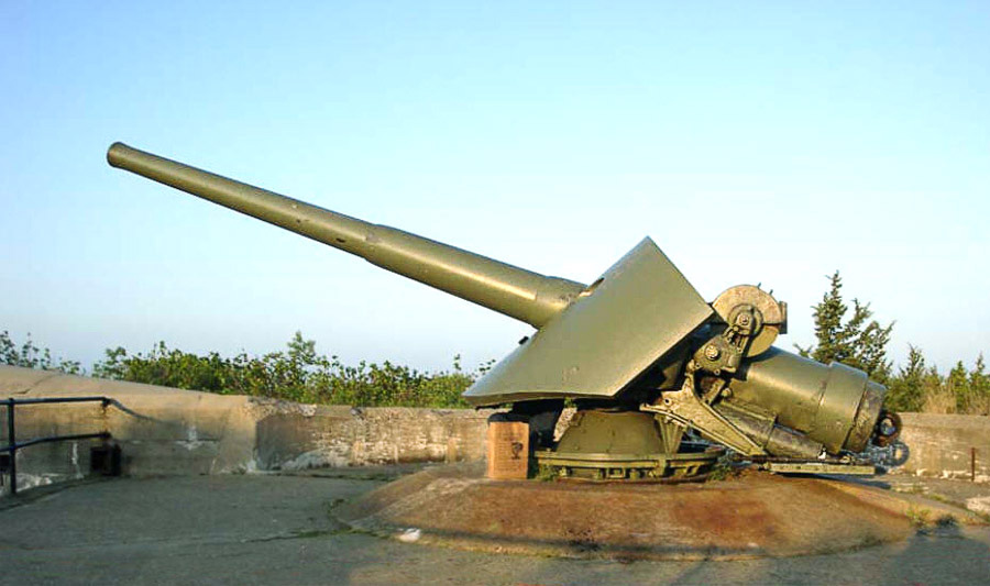
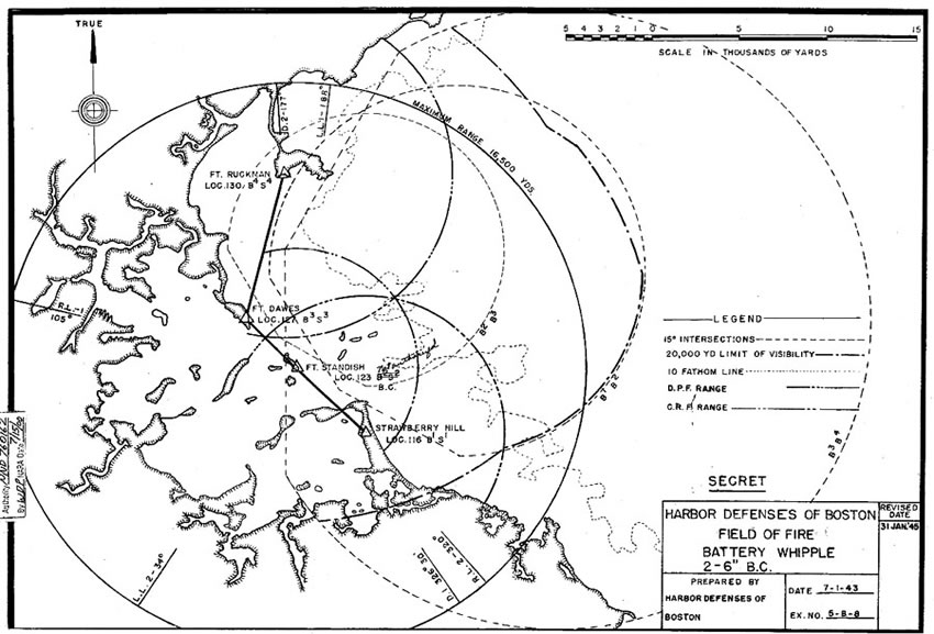
Slide 1 in the M1900 gallery shows a period photo of this gun, installed on its familiar pedistal mount, while Slides 2-5 are modern photos of M1900 guns that have survived to the present (at Ft. Hancock, NJ). According to the CDSG (ASD, p. 97), the gun weighed in at just under 10 tons, while the carriage added another 12 tons plus. [NOTE] The CDSG indicates that 45 of the older carriages were built, with 44 emplaced from 1902 to 1906. In the early years of the Endicott period, this was the weapon usually chosen for rapid fire defense against mid-size ships. Slide 6 in the M1900 gallery shows the ranges of the two M1900 guns of Btty Whipple at Ft. Standish in Boston Harbor (an arc from Swampscott in the north to North Scituate in the south). [NOTE]
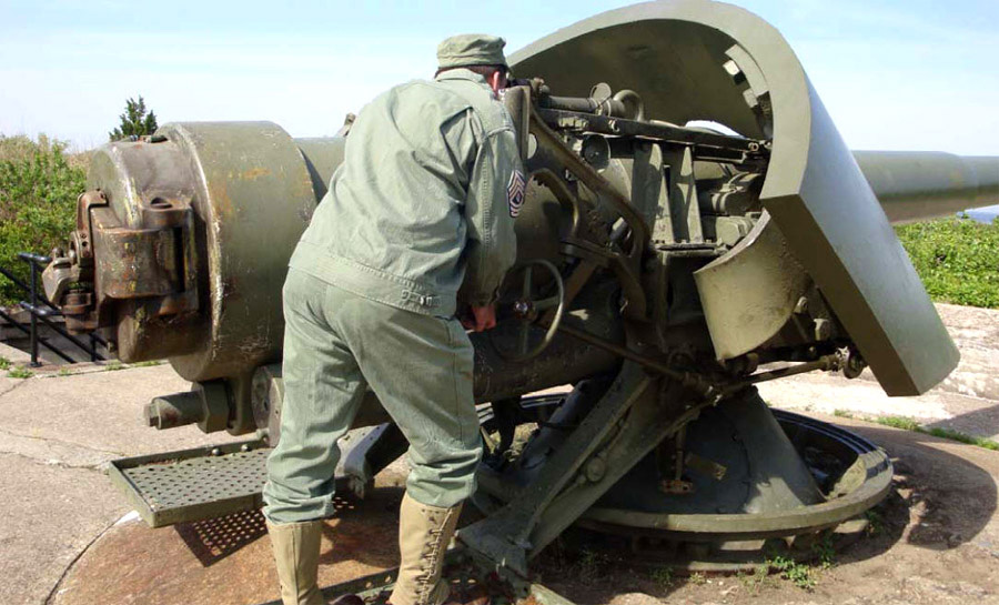
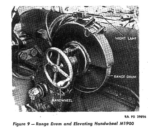
Elevating the gun was accomplished by turning a handwheel located on the left side of the breech (Slide 7). As the barrel elevated, an inter-connected range drum (Slides 7 and 10) turned as well, and the range (in yards) to the target could be read off through a window at the top of the drum, which was also lit for use at night. The M1900 could be elevated 20 degrees and depressed 5. Normal loading elevation was 10 degrees.
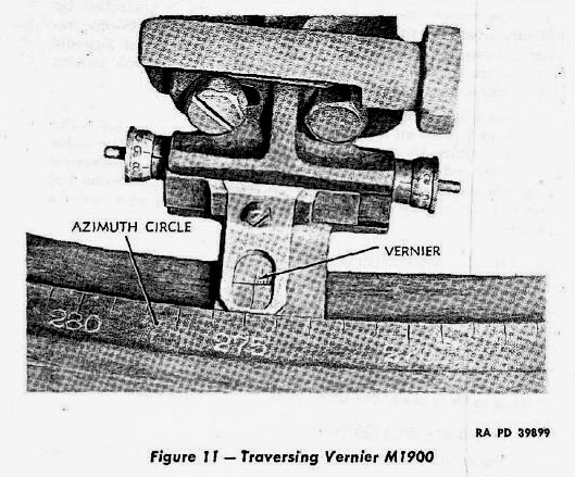
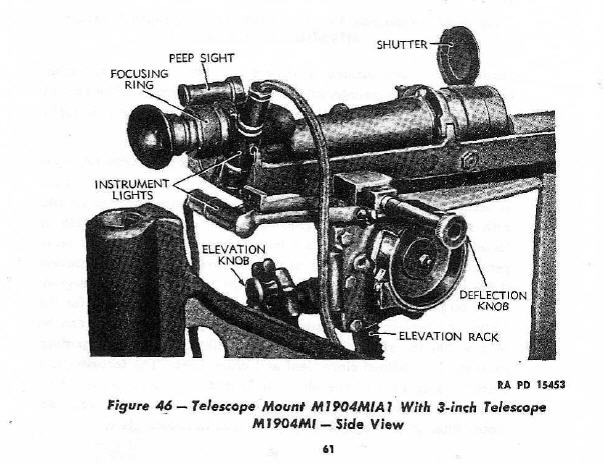
The gun was traversed (pointed in azimuth, or direction) by another handwheel (suspended from one of the two shoulder rests) located on the right side of the breech (Slide 4). The azimuth of pointing could be read off a vernier (Slide 8) that was mounted below the handwheel and turned along with the gun's pivot yoke, relative to an azimuth circle set on the gun's base. [NOTE] While capable of 360-degree fire, these guns were often installed with stops on the pedistal which limited their rotation (in order to avoid firing at local hazards). The weapon could be aimed through a telescopic sight (Slides 4, 9, and 10). The gun crew was protected by a semi-circular shield of steel plate that was 4.5 in. thick.
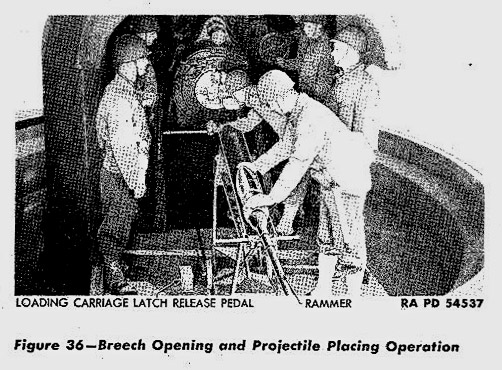
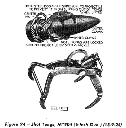
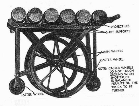
As with the larger Coast Artillery guns, firing the M1900 involved loading the projectile into the breech (Slide 9), using a 5.5 ft. rammer to seat it, following this with the separate propelling charge (a long, tubular powder bag, 6.75 in. by 42 in., weighing 33 lbs.), and then inserting the primer into a hole in the obturator (a part of the breechblock). The gun was fired electrically or by lanyard pull, and fired armor-piercing or high explosive shells that weighed between 90 lbs. and 108 lbs. These shells were stored in magazines near or below the guns. Leaving the magazines, the shells would often be hoisted by shell tongs (Slide 11) and then moved along steel beam trolleys to positions at which they could be moved, often using shot trucks (Slide 12), to shell hoists and/or to the loading platforms. Sometimes powder bags and shells were carried by hand up steep flights of stairs from the magazines to the gun positions, but many M1900 gun positions were eventually served by ammunition hoists.
The Model 1 differed from the older M1900 by having a greatly increased range (achieved by being able to be elevated higher), more sophisticaled fire control equipment (including powered elevation), and the capability of expelling powder gasses and residue from the gun with compressed air (making loading faster and safer). According to the CDSG (ASD, p. 104), the gun weighed in at just over 10 tons, while the M1 carriage added another 37 tons plus. The CDSG indicates that 143 carriages of the M1, M2, M3, and M4 types were built, with about 120 emplaced from 1941 to 1946.
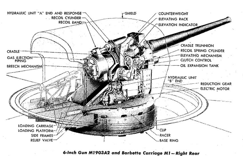
The first two slides in the Model 1 gallery below-left show drawings taken from its manual of the left and right sides of the gun (remember that the gun bore a variety of names because of its development history). [NOTE]
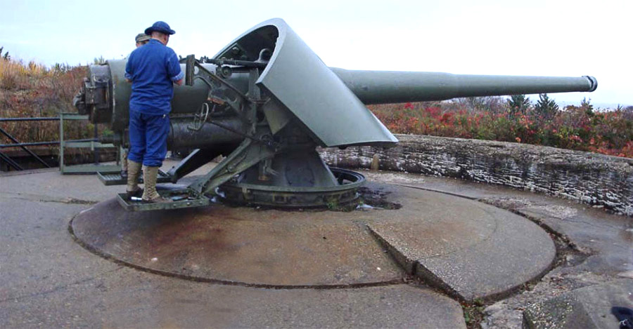
The Model 1 can be easily recognized by its bulbous all-around steel shield, which weighed 20 tons and surrounded the crew while they served the piece. The interior of this shield had three electric light fixtures and two built-in telephone circuits, plus a trouble light on a long cord for making repairs. Projectiles were carried to the breech on a four-wheeled carriage that ran on tracks that were part of the loading platform.
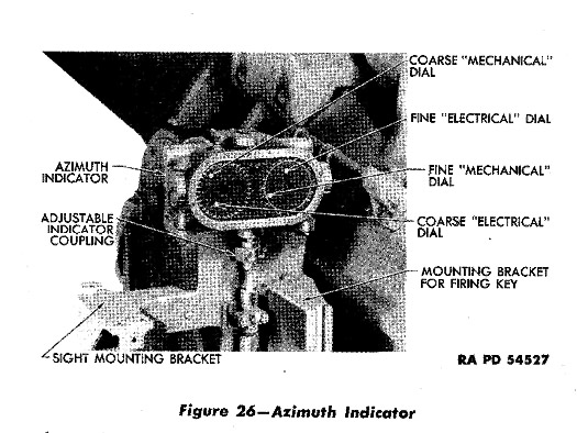
With the Model 1, both elevation and azimuth of the gun were set by having a crewman match the reading on an electrically-driven dial (which responded to data sent from a fire control center) with that on a mechanically-driven dial linked to the gun's yoke (see Model 1 gallery, Slide 3). Unlike the M1900, the elevating mechanism of the Model 1 was on the right side of the carriage, and could be operated (by a crewman called the range setter) via an electric-hydraulic power system or by a handwheel. Like the older model, the Model 1 was designed to be loaded at a 10 degree elevation, but it could be elevated much higher (to 47.5 degrees) and depressed 5 degrees. The traversing handwheel was located on the gun's left side, and was operated by a crewman called the gun pointer. Model 1 also had piping and an air compressor that operated a system designed to purge the gun of combustion gasses and bits of unburned power or powder bag, making it unnecessay to routinely swab out the gun during firing.
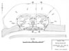 This plan, from the Army Engineers' 1945 Report of Completed Works for the battery, shows the gun platforms, sitting atop the casemated magazines, with the Battery Commander's station (the concrete "pulpit") between them. This plan shows the slightly enlarged gun platforms that resulted from the "modernization" in 1941.
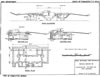 The top drawing gives a good idea of the exterior of the original battery, whiich is also shown in a 2010 photo in the next slide. This older vintage battery had no power generating capacity of its own, no integrated fire control (plotting room) spaces, and no capabilities for air scrubbing (to defense from chemical attack).l
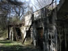 This photo looks WNW and up from the roadway in front (just south) of Btty McCook. The slit containing the concrete stairs to the Battery Commander's "pulpiut" is at top center. The window in the background led to an innor room, likely for officers. One of the armored steel doors to the magazines is visible in the foregrund. (PG 2010)
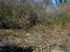 This photo shows the current condition of the gun platform for Gun 1 of Btty McCook. The yellow dot marks the approximate position of the center of the gun. Heavy growth of thorns and underbrush now makes it impossible even to see the waters of Boston Harbor from here. (PG 2010)
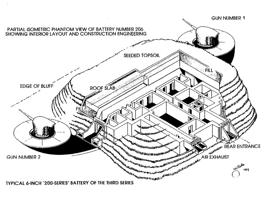
 This drawing, by Gerald Butler, shows an isometric, cutaway view of a typical WW2-era battery of 6-Inch Model 1 guns, this one being Btty 206 at East Point in Nahant, MA (HD of Boston). Ammunition was served from the magazines along the front corridor of the central traverse through the magazine doors near the guns and were stored in the "ready" alcoves to the left and right of these doors.
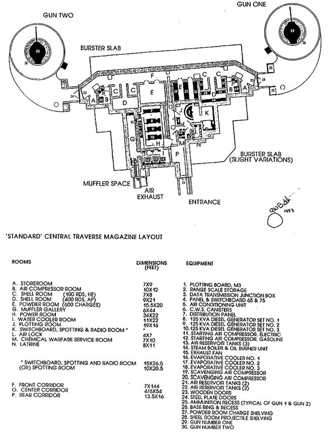
 This labeled drawing, again by Gerald Butler, shows the details of the central traverse of a typical WW2 200-Series battery of 6-Inch Model 1 guns (like that shown in Slide 4). This type of battery had exensive generating capacity (to power the guns and their air compressors), as well as spaces for a gun data computer and a back-up plotting board, as well as radio and phone communications. Equipment also existed to scrub the air and protect against chemical warfare.
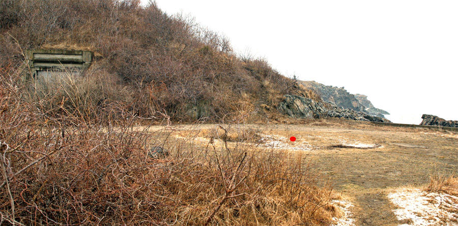
 This photo looks northeasterly across the former gun platform for Gun 1 of Btty 206 at East Point in Nahant, MA. The red dot marks the approximate center of the former gun. Portal on left is the entry from the gun platform to the magazines in the central traverse, which is covered by a tall mound of earth. The nearby ammunition recesses are obscured by brush. The battery was constructed right at the ocean's edge, with concrete works planted on the rocky ledges along the shore. The platform for Gun 2 is located dead ahead in this photo, on the other side of the central traverse, and has been heavily filled-in with dirt as part of later constructions projects. The central traverse is reportedly still visitable. with permission from Northeastern Univ., which manages the site as part of a large marine research facility. (PG 2010)
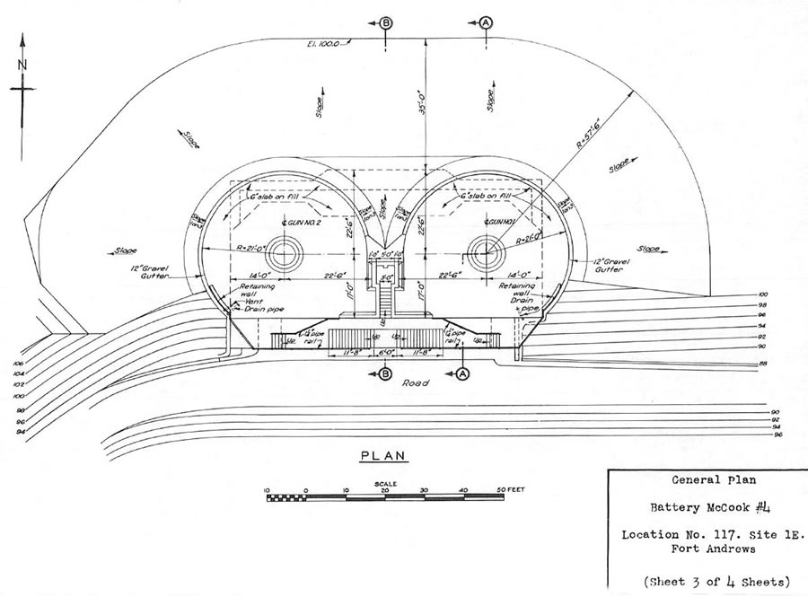
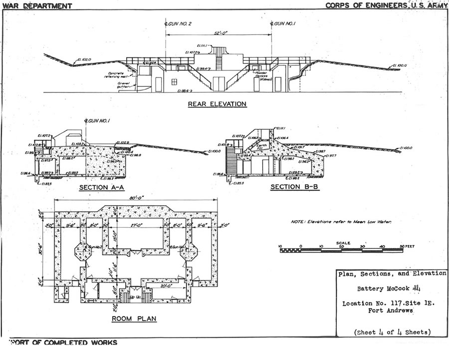


Slides 1 and 2 above show a plan drawing and several elevations for an emplacement of two older, M1900 6-inch guns, in this case Btty McCook at Ft. Andrews on Peddocks Island in Boston Harbor. Constructed between 1901 and 1904, this battery had its guns spaced rather closely together (52 ft. on center), with a Battery Commander's station in a concrete "pulpit"-type position between the two gun platforms. [NOTE] Below the guns were the casemated magazines and spaces for tool storage and simple offices for battery personnel. Originally, a hand-operated shell hoist lifted the shells (at about 100 lb. apiece) up to the gun platforms, but in 1932, this hoist was ordered removed. The gun platforms were extended toward the rear in 1941, providing more room for the gun crews to load and swab the guns.
Slide 3 is a photo, from 2010, of the front of Btty McCook, looking WNW and up from behind Gun 1. The ground surounding the battery, which was clear-cut in 1904, is now thickly overgrown with tall trees, brush, and heavy thorns, and Boston Harbor is no longer even visible from the battery (see Slide 4). The western stairs ascending the front of the battery to the gun platforms have entirely rusted away, and the eastern stairs are disappearing.
Slides 5 and 6 show two marvelous drawings by Gerry Butler of a typical example of the newer, so-called Series 200 batteries of Model 1 6-inch guns that were installed during WW2. Slide 5 is a cutaway isometric drawing of such a battery and Slide 6 is a labeled drawing of the interior of the central traverse of this type of emplacement. The battery design allowed for a good deal of more modern technology: a gun data computer and a plotting room for fire control, integrated power generation to run the guns' elevating motors and their compressed air breech-purging systems, and facilites for chemical warfare defense.
Multiple two-gun batteries of both types of 6-inch guns, the earlier M1900 and the later Model 1 (T2), were operational in in the defenses of Boston Harbor during WW2.
The older M1900 was emplaced both at Btty McCook, Ft. Andrews, on Peddocks Island (shown above) and at Btty Whipple, Ft. Standish, on Lovells Island. Firing drills for the crews of Btty McCook were held at Btty Whipple, because Whipple's guns could be fired without disturbing nearby residents and targets could be towed well out at sea.
There were three batteries of the newer Model 1 (T2) guns: Btty 206 in Nahant, on the North Shore (described above), Btty Jewell on Outer Brewster Island in the center of Boston Harbor, and Btty 208, the two guns at Fourth Cliff in Marshfield, on the South Shore (and the most southern battery in the harbor defenses). [NOTE] The installation on Outer Brewster included a fire control radar tower, which, along with the 6-inch guns, could reach well out to sea.
This author has not yet been able to visit the batteries at Outer Brewster or Fourth Cliff. The former requires a small private boat in order to land. The latter is managed by the U.S. Air Force as a recreational facility for staff from Hanscomb Field in Bedford, MA , but this public agency has so far not granted access to the site--a shame, since this battery is reportedly one of the most intact Series 200 batteries in the country.


-Btty-246-Ft-Columbia,WA_fs.jpg)